Workflow
The WEC-Sim workflow diagram below shows a high level view of WEC-Sim’s functionality. As a precursor, a WEC design must be defined in an input file and the Simulink model file. This input file is read by WEC-Sim which instantiates objects based on parameters defined in the input file. The objects are used in conjunction with WEC-Sim’s Simulink library during the time-domain simulation. User defined functions serve for easy post-processing and visualization of WEC-Sim’s output. A detailed description of this workflow is provided in the following sections. For information about the implementation and structure of the WEC-Sim source code, refer to the Code Structure section.
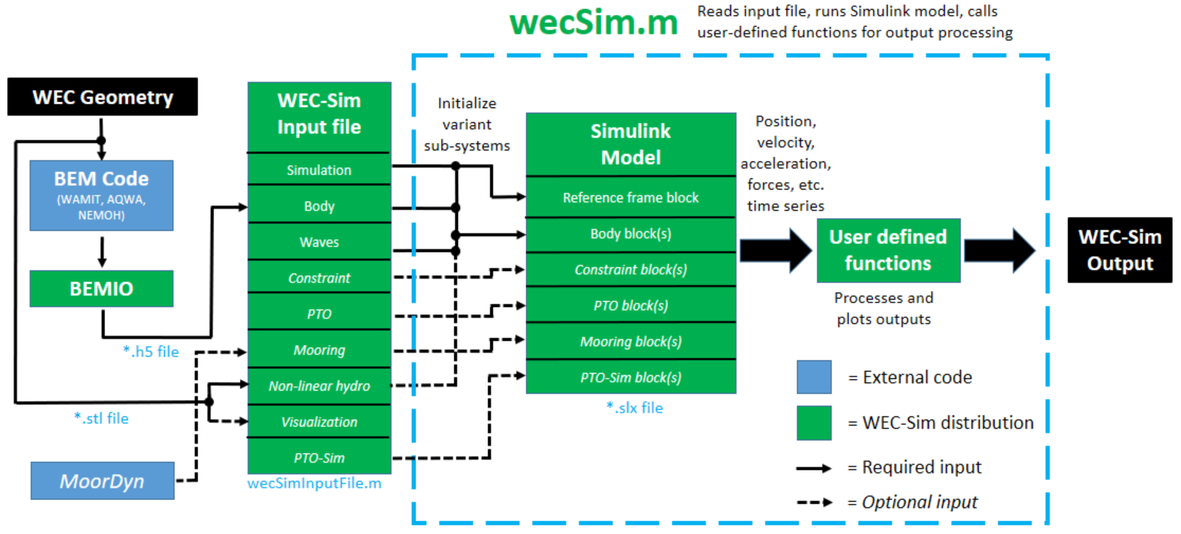
WEC-Sim Workflow Diagram
WEC-Sim Case Files
All files required for a WEC-Sim simulation must be contained within a case directory referred to as $CASE.
The case directory can be located anywhere on your computer.
It must include: geometry file(s), hydrodynamic data saved to a *.h5 data structure, a WEC-Sim input file, and a Simulink model of the device.
The table below lists the WEC-Sim case directory structure and required files.
File Type |
File Name |
Directory |
Geometry File(s) |
|
|
Hydrodynamic Data |
|
|
Input File |
|
|
Simulink Model |
|
|
Note
Where * denotes a user-specified file name.
Geometry File
WEC-Sim requires geometry file(s) (*.stl) that define each body.
The origin of the geometry file(s) must be at the body’s center of gravity.
When running WEC-Sim with linear hydrodynamics, the *.stl is only used for the Simscape Mechanics Explorer visualization.
However, when running WEC-Sim with nonlinear buoyancy and Froude-Krylov forces the STL mesh determines the instantaneous wetted surface at each time step.
In this nonlinear case, the quality of the STL mesh is critical, refer to the Nonlinear Buoyancy and Froude-Krylov Excitation section for more information.
Hydrodynamic Data
Hydrodynamic data for each body may be generated using a boundary element method (BEM) software.
WEC-Sim requires hydrodynamic data from a BEM solution in the form of a HDF5 file (*.h5).
This *.h5 hydrodynamic data file can be generated using the BEMIO pre-processor.
BEMIO (Boundary Element Method Input/Output) is a pre-processing software developed by the WEC-Sim team to parse BEM output files from WAMIT, NEMOH, Aqwa, and Capytaine into a data structure, saved as a *.h5 file, that can be read by WEC-Sim.
For more information about the BEMIO pre-processor, refer to the BEMIO section.
Input File
A WEC-Sim input file (wecSimInputFile.m) is required.
The input file MUST be named wecSimInputFile.m and placed within the case directory.
WEC-Sim uses object orientated programming to describe components of the WEC model;
the main structure of the input file consists of initializing the WEC-Sim objects and defining properties for each object.
The input file requires initialization and definition of the simulation and wave classes, at least one instance of the body class, and at least one instance of the constraint or PTO classes.
For details about WEC-Sim’s classes and available properties for each, refer to the WEC-Sim Classes section.
The WEC-Sim input file (wecSimInputFile.m) for the OSWEC example (WEC-Sim/examples/OSWEC/) is shown below.
WEC-Sim is an object oriented code and the input file reflects this by instantiating the WEC-Sim classes to create objects that are tied to the Simulink library.
The OSWEC input file initializes and defines properties for the simulation, body, constraint and pto classes.
%% Simulation Data
simu = simulationClass();                       % Initialize simulationClass
simu.simMechanicsFile = 'OSWEC.slx';            % Simulink Model File
simu.startTime = 0;                             % Simulation Start Time [s]
simu.rampTime = 100;                            % Wave Ramp Time [s]
simu.endTime=400;                               % Simulation End Time [s]
simu.dt = 0.1;                                  % Simulation Time-Step [s]

%% Wave Information
% Regular Waves
waves = waveClass('regular');                   % Initialize waveClass
waves.height = 2.5;                                  % Wave Height [m]
waves.period = 8;                                    % Wave Period [s]

%% Body Data
% Flap
body(1) = bodyClass('hydroData/oswec.h5');      % Initialize bodyClass for Flap
body(1).geometryFile = 'geometry/flap.stl';     % Geometry File
body(1).mass = 127000;                          % Mass [kg]
body(1).inertia = [1.85e6 1.85e6 1.85e6];  % Moment of Inertia [kg-m^2]

% Base
body(2) = bodyClass('hydroData/oswec.h5');      % Initialize bodyClass for Base
body(2).geometryFile = 'geometry/base.stl';     % Geometry File
body(2).mass = 999;                             % Fixed Body Mass
body(2).inertia = [999 999 999];                % Fixed Body Inertia

%% PTO and Constraint Parameters
% Fixed
constraint(1)= constraintClass('Constraint1');  % Initialize constraintClass for Constraint1
constraint(1).location = [0 0 -10];                  % Constraint Location [m]

% Rotational PTO
pto(1) = ptoClass('PTO1');                      % Initialize ptoClass for PTO1
pto(1).stiffness = 0;                           % PTO Stiffness [Nm/rad]
pto(1).damping = 0;                                   % PTO Damping [Nsm/rad]
pto(1).location = [0 0 -8.9];                        % PTO Location [m]
Additional examples are provided in the Tutorials section.
Simulink Model
In addition to an input file, WEC-Sim requires a Simulink model file (*.slx).
This Simulink model is defined using the WEC-Sim library blocks.
WEC-Sim’s library blocks are based on Simscape Multibody, refer to Simscape Multibody documentation for more information.
WEC-Sim library blocks contain masks that activate relevant parameters, based on the conditions specified in the wecSimInputFile.m.
The top level of the Simulink model contains Simscape physical signals that pass information between blocks in order to solve the relevant equations of motion.
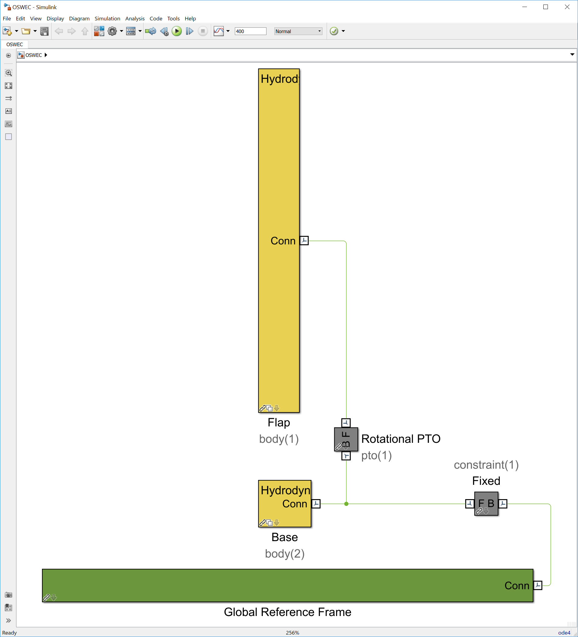
An example Simulink model file for the OSWEC is shown below. For more information about the OSWEC, and how to build WEC-Sim Simulink models, refer to the Tutorials section.
Running WEC-Sim
This section provides a description of the steps to run the WEC-Sim code. Refer to the WEC-Sim Workflow Diagram while following the steps to run WEC-Sim.
Step 1: Pre-Processing
In the pre-processing step, users need to create the WEC geometry, and run a BEM code to calculate the hydrodynamic coefficients.
Create WEC Geometry:
Create CAD models of the WEC geometry and export it to a
*.stlformat.The
*.stlfiles are used to visualize the WEC response in Simscape ExplorerThey are also used for Nonlinear Buoyancy and Froude-Krylov Excitation forces if the option is enabled.
Compute Hydrodynamic Coefficients: WEC-Sim requires frequency-domain hydrodynamic coefficients (e.g. added mass, radiation damping, and wave excitation).
The coefficients for each body may be generated using a boundary element method (BEM) code (e.g., WAMIT, NEMOH, Aqwa, or Capytaine).
WEC-Sim requires that all hydrodynamic coefficients must be specified at the center of gravity for each body.
Step 2: Generate Hydrodata File
In this step, users run BEMIO to convert
the hydrodynamic coefficients from their BEM solution into the *.h5 format
for WEC-Sim to read:
Run BEMIO: to generate
*.h5Hydrodynamic Coefficients for WEC-SimThe hydrodynamic coefficients for each body generated from the BEM code can be parsed into a
*.h5data structure using BEMIO, which was developed by the WEC-Sim team.BEMIO currently supports WAMIT, NEMOH, Aqwa, and Capytaine.
Note
If WAMIT is used:
The origin of the body coordinate system (XBODY, defined in
*.pot) as well as the mesh for each body must be at the center of gravity.The WAMIT mesh (
*.gdf) can be generated using Rhino or MultiSurf.More details on WAMIT setup are given in the WAMIT User Manual.
If NEMOH is used:
The origin of the mesh for each body (
*.dat) is located at the mean water surface.The location to output the hydrodynamic coefficients for each degree of freedom is defined in the
Nemoh.calfile.Please refer to NEMOH-Mesh webpage for more mesh generation details.
The NEMOH Mesh.exe code creates the
Hydrostatics.datandKH.datfiles (among other files) for one input body at a time. For the readNEMOH function to work correctly in the case of a multiple body system, the user must manually renameHydrostatics.datandKH.datfiles toHydrostatics_0.dat,Hydrostatics_1.dat, …, andKH_0.dat,KH_1.dat,…, corresponding to the body order specified in theNemoh.calfile.More details on NEMOH setup are given in the Nemoh Homepage.
If Aqwa is used:
The origin of the global coordinate system is at the mean water surface, and the origin of the body coordinate system for each body must be at the center of gravity (defined using the Aqwa GUI or in the
*.datinput file).In order to run BEMIO, Aqwa users must output both the default
*.LISfile and output the*.AH1hydrodynamic database file. Both of these files are reacquired to run BEMIO.More details on Aqwa setup are given in the Aqwa Reference Manual.
If Capytaine is used:
The origin of the mesh for each body (
*.dat) is located at the mean water surface.More details on Capytaine setup are given in the Capytaine webpage.
Note
Users are also able to specify their own hydrodynamic coefficients by
creating their own *.h5 file with customized hydrodynamic coefficients
following the *.h5 format created by BEMIO.
Note
We recommend installing HDFview https://www.hdfgroup.org/downloads/hdfview/
to view the *.h5 files generated by BEMIO.
Step 3: Build Simulink Model
In this step, users build their WEC-Sim Simulink model (*.slx) using the
WEC-Sim Library developed in Simulink/Simscape. The
*.slx Simulink model file must be located in the $CASE directory. The
figure below shows an example WEC-Sim Simulink model for the OSWEC tutorial.
Step 4: Write wecSimInputFile.m
The WEC-Sim input file must be located in the $CASE directory, and named
wecSimInputFile.m. The figure below shows an example of a WEC-Sim input
file. The input file specifies the simulation settings, body mass properties,
wave conditions, joints, and mooring. Additionally, the WEC-Sim input file must
specify the location of the WEC-Sim Simulink model (*.slx) file, the
geometry file(s) *.stl, and the hydrodynamic data file (*.h5) .
Step 5: Run WEC-Sim
Lastly, WEC-Sim can be executed from the $CASE directory by typing wecSim from the Command Window:
>> wecSim
Refer to WEC-Sim Examples for more details on how to run the examples.
Users may also run WEC-Sim from Simulink, or use the commands wecSimMCR,
wecSimPCT, and wecSimFcn as described in the advanced features
sections Running from Simulink,
Multiple Condition Runs (MCR), Parallel Computing Toolbox (PCT),
and Running as Function.
Note
The WEC-Sim source code is located in the $WECSIM directory, but
WEC-Sim must be executed from the $CASE directory.
The MATLAB path must include the WEC-Sim source directory.